
The Prytz planimeter, commonly called the 'hatchet' planimeter, as it somewhat resembles a crude hatchet, is a device used to measure area of a drawing. It can be used for determining areas on a map, for example determining surface area of a lake, or on blueprints, for such things as calculating the area of sheetmetal or cloth needed to cover something. For objects of irregular cross section, the planimeter can be used to calculate the area of that cross section, to determine volume. Many different planimeter designs exist. This is the simplest. It is as accurate as more complicated instruments, but less forgiving of user errors and sloppy technique, so has fallen into disuse. Still, its simplicity, ease of construction, and durability lend it well to use by tinkers and those who have to work under all sorts of conditions, not just in an air-conditioned, well lit drafting studio.
Standard disclaimer: This project and others available on this site uses heat, tools, chemicals, and open flames. You are responsible for taking all applicable safety precautions, and applying common sense. Since I have no control over how you do things in your own shop, or what precautions you choose to use or not use, and I'm not there to hold your hand, it's not my fault if you hurt yourself.
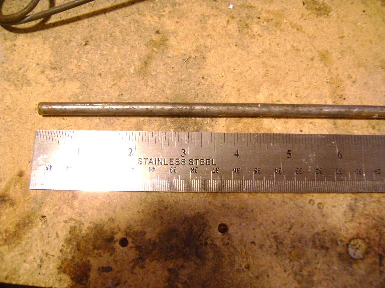
I had a piece of 1/4 inch mild steel rod kicking around in the garage. It was about two feet long. I didn't bother measuring it before I cut it to length. Any length will work, but you'll need enough for the tracing legs, plus the arm. Since you'll need to use the length of the arm in calculations, it's good to make it a convenient length, like exactly ten inches, or 25 centimeters, or such. No point in making your math harder than it has to be. I also had a scrap of brass tube and a bit of plywood about. I used fast epoxy to put the planchet together.
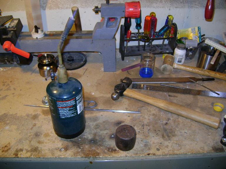
This project doesn't need any fancy or expensive tools. I deliberately didn't bring out anything exotic for this. I used a pair of bolt clippers to cut the rod to length, a file, a hammer, and a blowtorch. As an anvil I used a lump of hard steel salvaged from an industrial roller bearing. I used a fretsaw to cut out the planchet parts. I had some sandpaper for shining up the metal and taking splinters off the wood. Some simple drafting tools, such as a ruler, a square, and a pencil are needed for calibration. I used a metal straight edge for drawing, and an architectural rule graduated in 50ths of an inch for measuring. If your ruler is metric, you'll need to work to 1/10th of a millimeter. If your ruler is american, you'll need to reduce your 16ths or 32nds to a decimal fraction for calculation.
I decided to make the legs of the planimeter about 3 inches long, and the arm 10 inches. Ten inches makes for easy calculations, as I can just move the decimal point when calculating area. More about that later though. I marked off three inches from one end, scribed a line with the file, marked another ten and a half inches, made another mark, then marked the final three inches. I made the arm ten and a half inches long, as the bends will use up some length. These measurements don't have to be awfully precise. Fine adjustment will be done later.
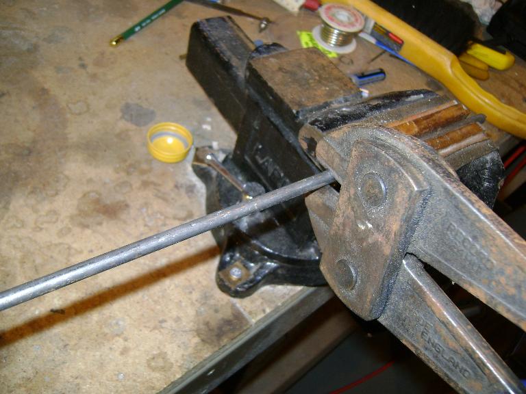
I clamped the rod in the vise, and used a pair of bolt clippers to cut it. I could have used a hacksaw, a cold chisel, cutting torch, or just nicked it deeply with the file and broken it off. Bolt clippers are fast though, and leave an end that's not too ragged.
After it's cut to length, it needs a point on one end, and the point should be rather slender. A short, wide point would work, but would obstruct the view of the lines it needs to trace. I started by filing one side down almost to the centerline, flipped it over and did the same to the other side. Here it is half finished.
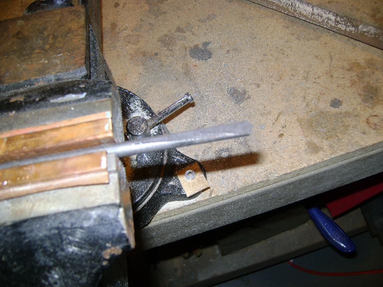
After I had two sides filed down to a taper, I turned it 90 degrees and brought the edges in. I did it this way so that I could keep the end of the point close to the center line of the rod, which would make it easier to line things up later.
One I had the point filed down to a square cross section, I took the corners off the square to make an octagon, took the corners off that again, and so forth, until I had it pretty close to a circular cross section all the way down. It really doesn't have to be this regular. The square point would have worked fine. You want the point to be sharp enough to easily trace fine lines, but not sharp enough to cut into the paper or to impale a fingertip on. Once you've gotten it filed down, take some fine sandpaper and knock the sharpness back a bit. I made mine somewhat smaller than half the size of the ball on the end of a ballpoint pen. This is a matter of personal preference, really.

Now its time to get to blacksmithing and put a knife edge on the other end. Here's my forge! A blowtorch for heat, a hammer, and a lump of metal. No point in getting out the big guns for this, or making it seem like this takes complicated tools. Just about any heat source would work here. You could put the end of the rod in a charcoal grill or hibachi, heat it on a gas stove, stick it in your campfire, etc.
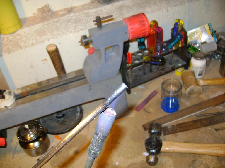
Holding the rod obliquely in the flame lets more of it rest in the flame, and heats it faster. The camera doesn't show it, but this is glowing a dark red. It's almost ready to hammer.
I don't have any pictures of the forging process, as it takes both hands. It's pretty self explanatory. You whack the steel to flatten it into a flared out wedge shape, thin on the outside edge. As soon as it stops glowing, stop hammering on it and put it back into the flame. It's a lot harder to make the metal move when it's not at least red hot, and the colder you let it get, the longer it takes to reheat. This took three heats, and about 2 minutes to do.

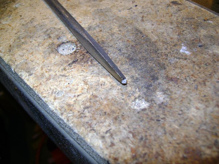
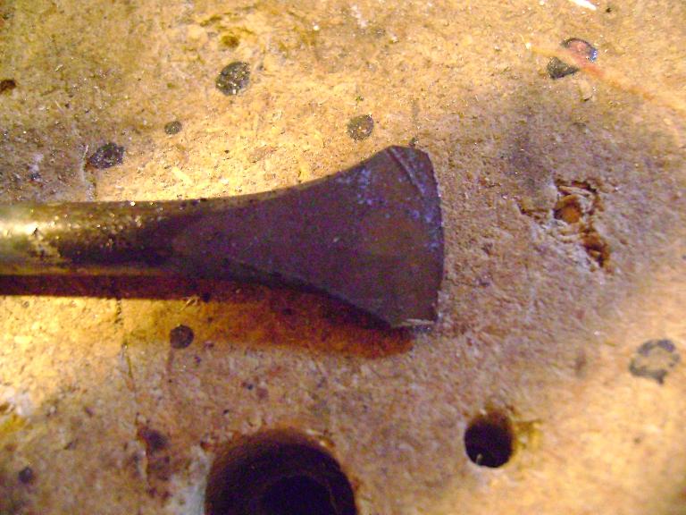
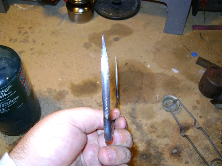
Here's how it should look from the side. You want it to taper down to a thin edge, and for that edge to be close to the centerline of the rod. If it isn't lined up, you can always heat it up again and adjust it with the hammer.

I took the file and made the edge a little less rockered, and took the sharp corners off the outside edges. The edge doesn't need to be sharply curved, just enough that it rides over the paper without the ends of the blade digging in.
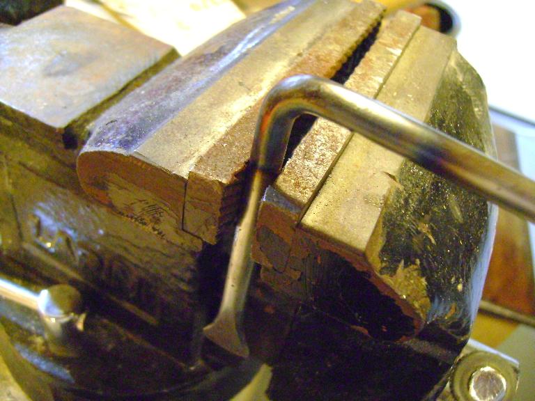
I clamped it just below the three inch mark I made at the beginning, heated it to a dull red, and made a right angle bend. The metal bends easily at a dull red heat. It's important at this point to keep the blade edge parallel to the arm, but if this is a bit off, it can be adjusted later.
I did the same thing at the point end. At this point, you can sight down the arm and make sure that the blade and the point are lined up. If you sight down the edge of the blade, it should be lined up with the point, and the legs should be pointing in the same direction. Here's how it should look. At this point you can sharpen the edge, polish off the oxidation with sandpaper, and make it shiny. Be sure while sharpening the edge to take equal amounts off both sides so it stays lined up like you want it. Sight down it as you work to keep it lined up with the point.
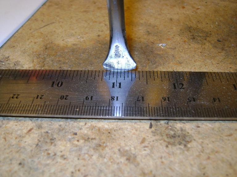
Once everything is lined up nicely, it needs calibrated. The first step of this is to adjust the arm length to some definite measurement. I chose ten inches for ease of calculation, but after I bent the legs, the arm was just a hair short, so I bent the legs out until the point where the blade will touch the paper is as close to exactly ten inches as I can make it. Note that in this picture, I have the point resting on the '1' of the ruler, not the '0', because the zero is off the end of the rule, and isn't as accurate. That means that ten inches here is from one to eleven, not zero to ten.
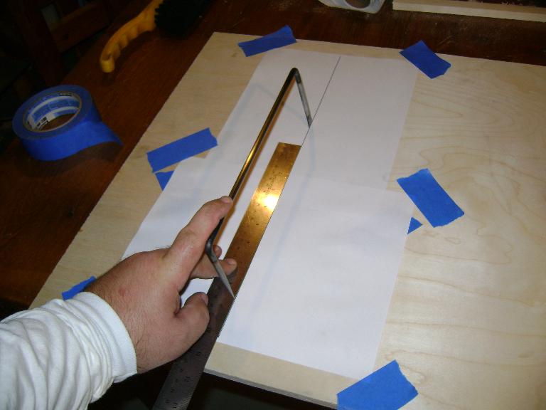
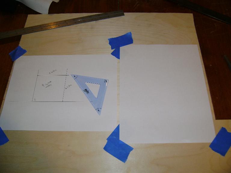
The second step in calibration is to ensure that the blade is perfectly aligned with the point and tracks well on the paper. For this, we go to the drawing board. I taped down two pieces of paper, and drew a straight line with a rule.

I lined the rule up with the the near half of the line, and placed the blade on the upper half of the line. When I trace the point back and forth down the rule, the blade should stay on the line and track smoothly, rather than veering back and forth, or catching and tearing. If it veers, it'll need to be better aligned with the point. For big changes, you'll need to heat the leg to red heat and twist the edge into alignment. For small changes, you might be able to file it again.
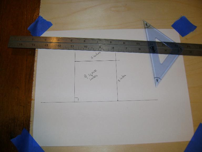
Once you've confirmed that the blade is tracking correctly with the point, the next step is to get some practice in, and confirm that the whole thing works. For this, get out your drafting tools and draw a shape of definite area. The planimeter is able to measure shapes half the length of its arm or smaller, so in this case, keep the maximum dimension of the shape under five inches. I drew a square three inches on a side, for a nine inch area.
The blade is going to scratch the paper up a bit, so even if you are using a big sheet of paper you'll want to put down another one for the blade to run on. Make sure your paper can't move; tape the corners down.
Find the approximate center of the area. It doesn't have to be exact, just somewhere in the center of the area. Make a mark at this point, and draw a line from it to the edge of the area. This center-ish point is going to be your starting and ending point, and the line from it to the edge of the area will be how you trace out from the center and back in. Because you're tracing the line both ways and it has no area, it should cancel out and not show up in calculations. This line doesn't have to be precise. I just drew it by hand. It should be straight-ish so it's easy to trace; no point in making your work harder than it has to be.

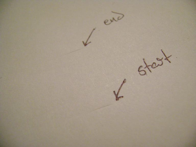
Take the point of the planimeter and place it on the center point of your area. Take the arm and stretch it out to your second piece of paper. It should be well centered on the paper, so it won't run off the edges as you work. Push down on the blade a bit to make a mark. Take the point, and trace it from the center to the edge of the figure, then around the perimeter either clockwise or counterclockwise, and back to the center. Keep the leg as vertical as possible while you're doing this, and grip the leg just tightly enough to keep it vertical and move it around the figure. If you slant it over, the blade won't track correctly, and if you grip it too tightly, you may pop the blade out of the channel it's scribing in the paper. Both these will lead to errors. Once you're back to the center, push down on the blade again to make a second mark in the paper. If you want to double check that you've done it right or you want to average multiple tries, do the procedure again, but go around the figure in the opposite direction from what you did the first time. This way, any errors in movement have a chance to cancel out.

Here's what the marks will look like. You'll want to measure from the center of the mark to the center of the other. For the greatest accuracy, measure the length along a line with a radius equal to the arm length of your planimeter. Some planimeters come with a curved ruler for this purpose. In practice, a straight ruler gives the same result, assuming the distance measured is a negligible fraction of the planimeter arm length. As the area should be scaled to be no more than half the arm length in any dimension, its maximum area is going to be around 25 square inches, for a distance between marks of 2.5 inches, and this isn't long enough for a meaningful difference between a straight line and a line of 10 inch radius.
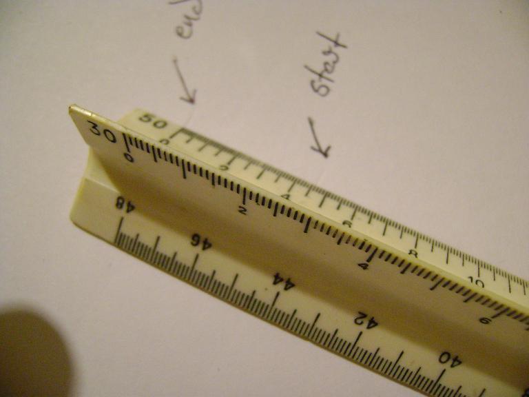
I measured the distance between the marks with the smallest division ruler I had. It's hard to see due to the camera looking on from an angle, giving a parallax error, but the measurement here is 45 fiftieths of an inch, or 0.9 inches, near as I can figure it with this ruler. To get the area of the drawing you traced, multiply this number by the length of your planimeter's arm. This is why ten inches is a convenient arm length; makes for easy multiplication of decimal numbers. Ten inches multiplied by 0.9 equals nine square inches. Since I already knew that the figure I drew was three by three, this isn't as much surprising as a pleasant confirmation that I'm doing a good job with the planimeter. As a disclaimer, I've used these many times before, and practiced half a dozen times with this one before taking a picture of the results for the record. I was off several times by as much as two fiftieths of an inch.
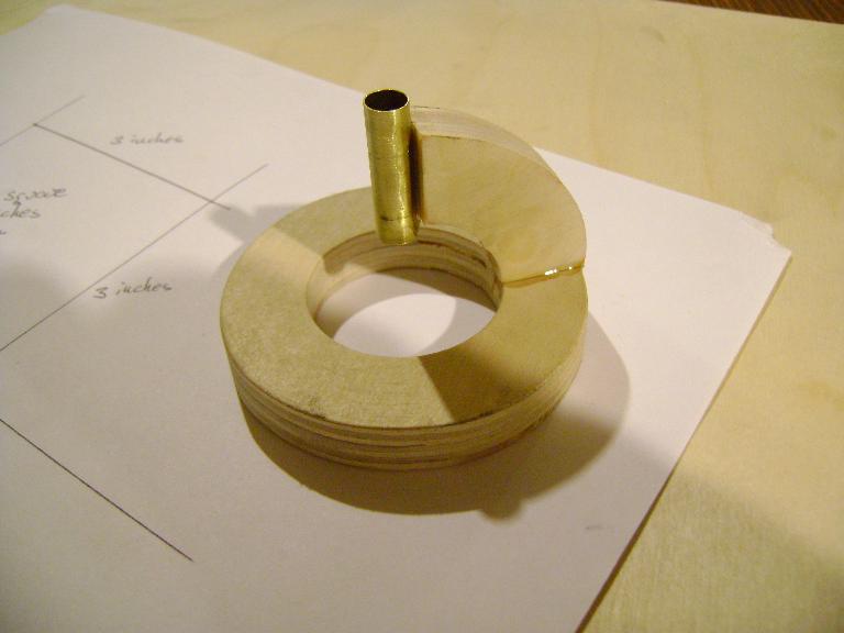
The planimeter can be used just as is, as long as you practice with it to make sure you're keeping the tracing leg vertical and keeping a light enough touch to avoid making the knife edge jump around. To help with this and to reduce errors even further, a lot of commercial sets came with a planchet that allowed the tracing leg to be moved around without directly touching it, and ensured that it was vertical at all times, even if the user's concentration lapsed. To make one, I traced out two concentric circles and a section of an arc of the same radius on a scrap of plywood. I cut them out with a fretsaw, sanded them smooth, and used fast epoxy to glue them together. For a guide, I epoxied on a scrap of brass tubing that was a close fit around the tracing leg of the planimeter. Here's what it looks like.
This wasn't a hard project. I took a lot of care to make sure things were well lined up and calibrated. This is certainly less time consuming than integrating to find the area of a shape. The accuracy depends on the user's skill and attention, but that's common to damn near anything...
Find more Tinker Projects: